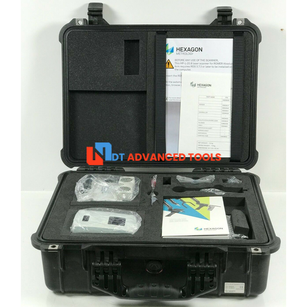
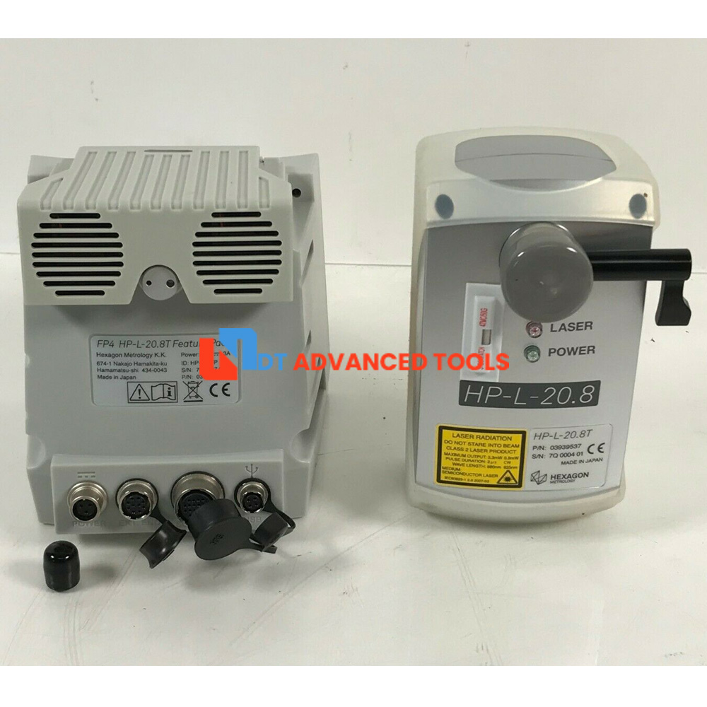
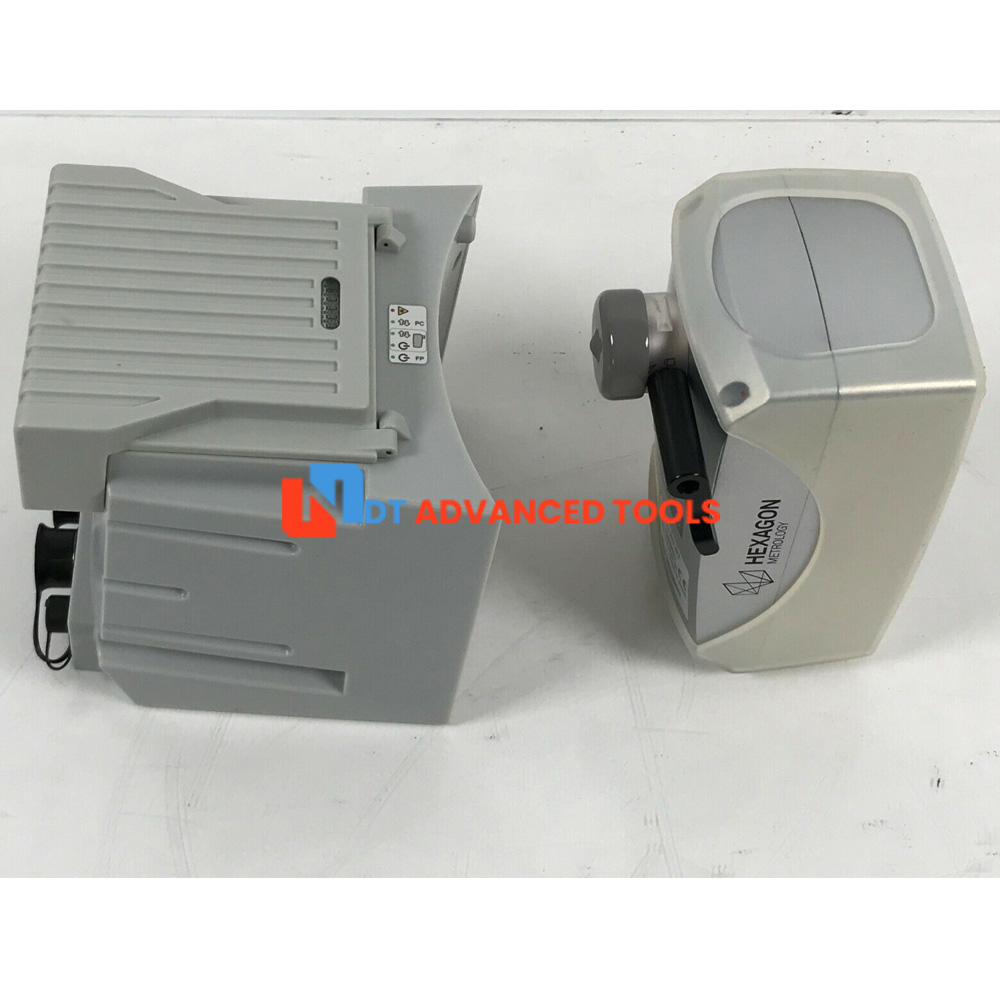
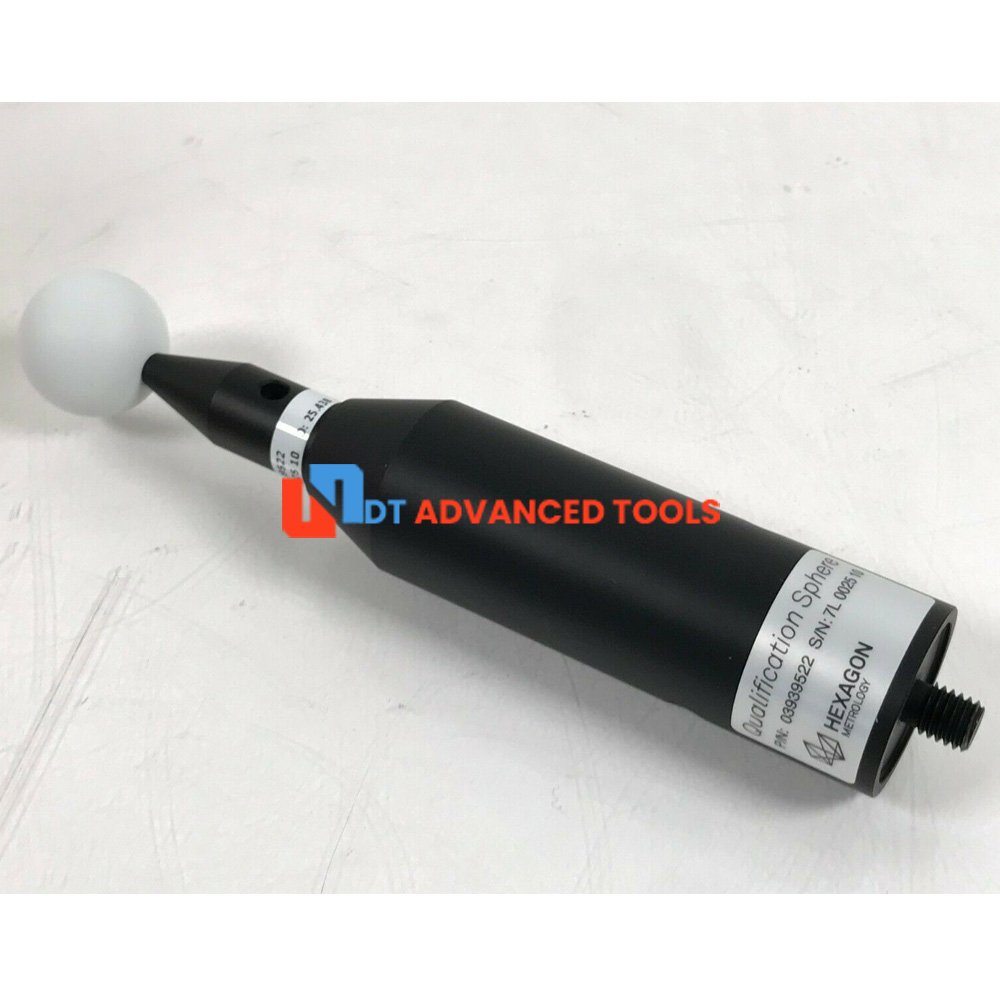
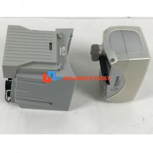
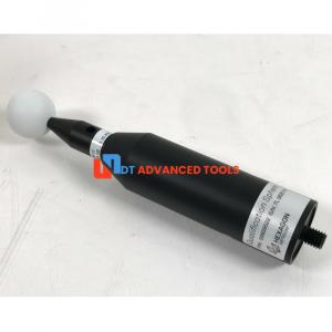
Hexagon HP-L-20.8T Laser Scanner
Sell used Hexagon HP-L-20.8T Laser Scanner, in good condition, 30 days return available.
Condition: UsedHP-L-20.8T laser scanners deliver maximum performance for complex surfaces and workpieces made of materials that are difficult to measure. These flexible laser scanners record precisely even at the highest speeds. Among the main applications: Checking the characteristics of thin-walled components, sheet metal parts, measuring freeform surfaces and reverse engineering.
BENEFITS OF THE HP-L LASER SCANNER:
Gathers high-density point cloud data by automatically adjusting the light intensity
Offers reliable measurement of complex surfaces, such as parts ranging from very dark colours to extremely shiny finishes
Supports higher productivity thanks to shorter measuring times
HP-L relies on Flying-Dot Technology, which is superior to conventional line scanners: as the light intensity is automatically adjusted for point by point. This means the laser scanners are less sensitive to ambient light and surface changes, and generate point clouds of the highest density. As well as this, the line width can be varied as needed from 24 mm to 220 mm. The point-to-point distance is varying depending on the chosen line-width.
The sensors are specified to the latest ISO standard 10360-8:2013 for optical laser sensors. Thanks to its TKJ adapter, The HP-L-20.8T is primarily offered on the ROMER Absolute Arm as a portable measuring solution. It can also be used on Hexagon CMMs with an adapter.
Specifications
| Manufacturer | Hexagon |
| Model | HP-L-20.8T |
| Laser protection class | 2 (IEC 60825-1: 2007) |
| Laser | Visibly red, (690 nm) |
| Standoff and depth (Z) | 180 ± 40 mm |
| PForm.Sph.D95%:Tr:ODS (MPL) Probe dispersion value | 36 µm |
| PForm.Sph.1x25:Tr:ODS (MPE) Probing form error | 25 µm |
| Lines per second | 100 Hz (max.) |
| Data rate | 150 000 pts/sec (max.) |
| Ambient light of the sensor | 40 000 lx |
| Operating temperature | +5 to +45 °C (41 to 113° F) |
| Declared accuracy temperature range | +15 to +32 °C (59 to 90° F) |
| Relative humidity | 90% non-condensing |
| Detection of signals | positive half-wave, radio mode |
| Power supply | DC 18 to 28 V, 170 to 200 mA, protected against polarity reversal |
| Protection against dust and water | IP64 (IEC 60529) except for warm-up connection |
| Dimensions (L x W x H) | 137x76x85 mm |
| Weight | 410 g |
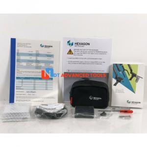
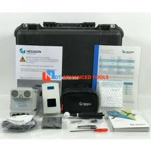
Included:
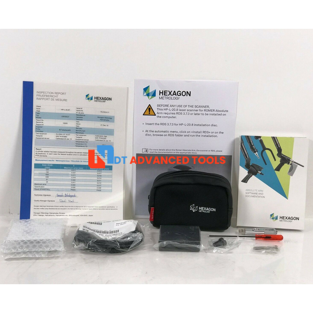
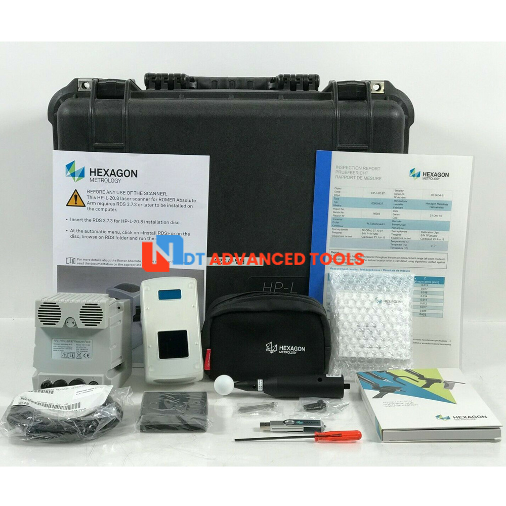
- HP-L-20.8T
- Cable
- Software
- Operating manual
- Case
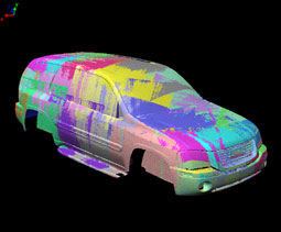 |
What can you do with 3D laser scanning? Laser scanning in an industrial metrology context can be used for several distinct purposes. ROMER seven axis SI Absolute Arms is equipped with PC-DMIS software and 3D laser scanners, accurately performs all of these functions in a single system. Its Absolute Encoders 'know' where the arm is at all times (eliminating homing procedures) and zero-G counterbalance ergonomics make it seem to float in the operator's hand. Laser scanner output creates a three-dimensional model of a surface, which due to its high density (often millions of points) is called a ”point cloud” or ”cloud of points”. Shows a large point cloud set representing an entire vehicle. The different colors represent different individual scanning passes on the part. |
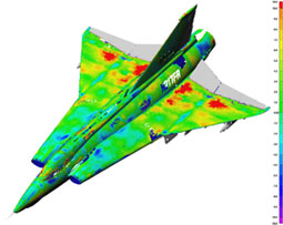 |
Target inspection and validation The 3D point cloud created by the 7 axis Absolute Arm combined with PC-DMIS can be used for dimensional inspection or GD&T, and the results compared againt nominal CAD values. With Cloud-to-CAD comparison, large point clouds can be overlaid on the CAD model for fast visual inspection of deviations (sometimes called a ”weathermap” or ”color map” see. Laser scanning can also be used for traditional (non-CAD) inspection using feature construction and dimensioning. Example inspection and validation applications:
|
| Reverse engineering Reverse Engineering is the process of taking a physical part, measuring it to determine its characteristics and the processing the data to creating a CAD model. This is often used in cases where the product design process has significant manual operation, such automotive design. Despite the advances in CAD, many designs still start life as a physical model which then needs to be turned into electronic form. Point clouds generated by laser scanning are processed in various ways to make them ready for conversion to CAD. Reverse Engineering software such as PC-DMIS Reshaper is used to create or import the scanned point cloud, manipulate, mathematically smooth and combine the scanned data so a representative surface model can be created. Example reverse engineering applications:
One-off replicas may not require creation of a full CAD model. Stereo-lithography models or CAM-based milling in many cases can be done directly from the point cloud scan data or the mesh model. Basic resizing and scaling of the model may be possible. CAM software is used to read the scan cloud data and produce machining instructions for CNC machine tools.
Scanning speed depends significantly on the probe and the probe's field of view. On laser probes in general, you will be able to see the points collected ”on screen” in real time. Sometimes this is referred to as ”painting the part”. Making scans at different angles to ensure all the relevant geometry is captured often results in a point cloud such as the one captured of the Liberty Bell, where it looks like someone went crazy with the spray paint. Also significant to the overall speed is the scanner's number of points per second capability, the scanning path width, and the the density of points per line. The animation below compares the difference between a two different scanners, one with a narrow stripe and one with a wide stripe, capturing a 1 meter square flat plate at a mid field of view. The scanner with a wider (105mm) line width at mid-field of view, captures the surface in just under 3 minutes, where the scanner with the narrower line width would take over 13 minutes for the same part. The application can be a contributing factor to scanner choice. Applications where speed and coverage are extremely important, but fine details are not, may require a scanner with a higher speed. Other applications with smaller, more complex parts, may work better with a smaller stripe width. Some scanners, such as the HP-L-20.8 allows the user to select a stripe width that best matches the application. |
|
|
Are more points better? Does ambient light affect the sensor?
|
|
| Do surface conditions affect the laser sensor? Traditionally measurement accuracy was affected by surface finishes. Highly polished chrome and shiny black surfaces were the most difficult to scan. Multi-colored surfaces or surfaces that transition in reflectivity can also cause problems for many scanners. ROMER arms equipped with laser scanners employ tools to cope with these situations, allowing most surface finishes and colors to be scanned successfully. Our premium HP-L-20.8 sensor employs automatic exposure control and flying dot technology to allow it to adjust automatically in real time to changes in material color and reflectivity, making it easy to scan nearly anything successfully. In the picture on the right, a part with three different colors and surface finishes and differing levels of reflectivity is easily scanned with the HP-L-20.8. Do you have to powder the parts? |
|
|
Filtered vs. Unfiltered data... What's the difference, really? When I scan a part, do I get a CAD model when I'm done? |
|
