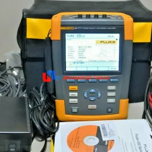
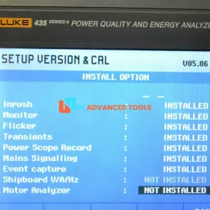
Fluke 435-II Power Quality and Energy Analyzer
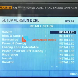
Sell used Fluke 435-II Power Quality and Energy Analyzer with Harmonics. Tested and working good conditions.
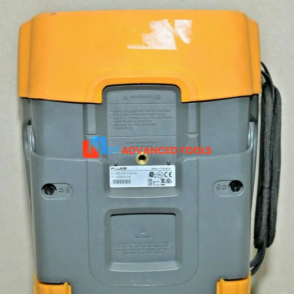
Condition: Used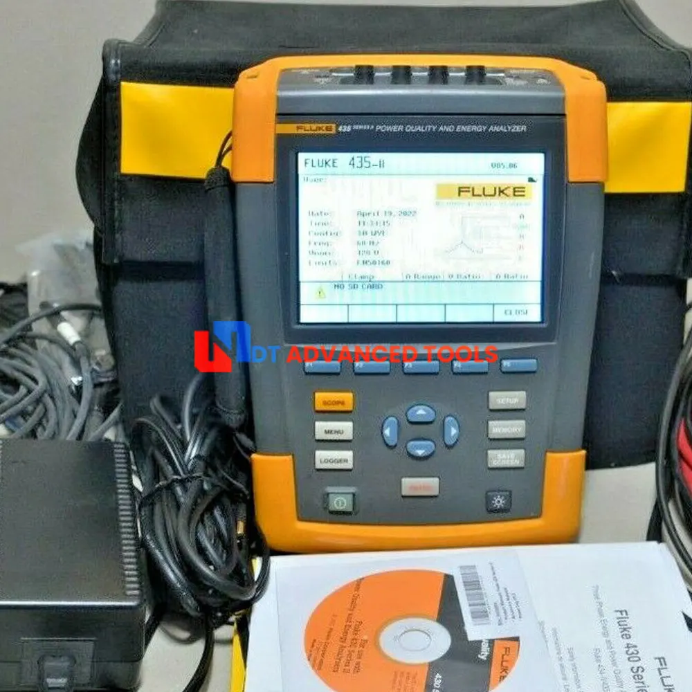


The new 430 Series II Power Quality and Energy Analyzers offer the best in power quality analysis and introduce, for the first time ever, the ability to monetarily quantify energy losses.
The new Fluke 434, 435 and 437 Series II models help locate, predict, prevent, and troubleshoot power quality problems in three-phase and single-phase power distribution systems. Additionally, the Fluke-patented energy loss algorithm, Unified Power Measurement, measures and quantifies energy losses due to harmonics and unbalance issues, allowing the user to pinpoint the origin of energy waste within a system.
Unified Power Measurement
Fluke’s patented Unified Power Measurement system (UPM) provides the most comprehensive view of power available, measuring:
- Parameters of Classical Power (Steinmetz 1897) and IEEE 1459-2000 Power
- Detailed Loss Analysis
- Unbalance Analysis
These UPM calculations are used to quantify
the fiscal cost of energy loss caused by power
quality issues. The calculations are computed,
along with other facility-specific information,
by an Energy Loss Calculator that ultimately
determines how much money a facility loses
due to wasted energy.
Energy savings
Traditionally energy savings are achieved by monitoring and targeting, or in other words, by finding the major loads in a facility and optimiz ing their operation. The cost of power quality
could only be quantified in terms of downtime caused by lost production and damage to electri cal equipment. The Unified Power Measurement (UPM) method now goes beyond this to achieve energy savings by discovering the energy waste caused by power quality issues. Using the Unified Power Measurement, Fluke’s Energy Loss Calculator (see screen shot below) will determine how much money a facility is losing due to waste energy.
Unbalance
PM gives a more comprehensive breakdown of the energy consumed in the plant. In addition to measuring reactive power (caused by poor power factor), UPM also measures the energy waste caused by unbalance; the effect of unevenly loading each phase in three-phase systems. Unbalance can often be corrected by reconnecting loads on different phases to ensure the
current drawn on each phase is as equal as possible. Unbalance can also be corrected by installing an unbalance reactance device (or filter), that will minimize the effects. Correcting unbalance should be basic good housekeeping in the facility as unbalance problems can cause motor failure or shorten equipment life expectancy. Unbalance also wastes energy. Using
UPM can minimize or eliminate that energy waste, thus saving money.
Harmonics
UPM also provides details of the energy wasted in your facility due to the presence of harmonics. Harmonics may be present in your facility due to the loads you operate or may be caused by loads in adjacent facilities. The presence of harmonics in your facility can lead to:
- Overheating transformers and conductors
- Nuisance tripping of circuit breakers
- Early failures of electrical equipment
Quantifying the cost of wasted energy due to the presence of harmonics simplifies the return-oninvestment calculation needed to justify purchasing harmonic filters. By installing a harmonic
filter the ill effects of harmonics can be reduced and energy waste eliminated, resulting in lower operational costs and more reliable operation.
Technical Data
| Energy loss calculator | Classic active and reactive power measurements, unbalance and harmonic power, are quantified to pinpoint true system energy losses in dollars (other local currencies available). |
| Power inverter efficiency | Simultaneously measure AC output power and DC input power for power electronics systems using optional DC clamp. |
| PowerWave data capture | 435 and 437 Series II analyzers capture fast RMS data, show half-cycle and waveforms to characterize electrical system dynamics (generator start-ups, UPS switching etc.). |
| Waveform capture | 435 and 437 Series II models capture 50/60 cycles (50/60Hz) of each event that is detected in all modes, without set-up. |
| Automatic Transient Mode | 435 and 437 Series II analyzers capture 200 kHz waveform data on all phases simultaneously up to 6 kV. |
| Fully Class-A compliant | 435 and 437 Series II analyzers conduct tests according to the stringent international IEC 61000-4-30 Class-A standard. |
| Mains signaling | 435 and 437 Series II analyzers measure interference from ripple control signals at specific frequencies. |
| 400 Hz measurement | 437 Series II analyzer captures power quality measurements for avionic and military power systems. |
| Troubleshoot | Analyze the trends using the cursors and zoom tools. |
| Highest safety rating in the industry | 600 V CAT IV/1000 V CAT III rated for use at the service entrance. |
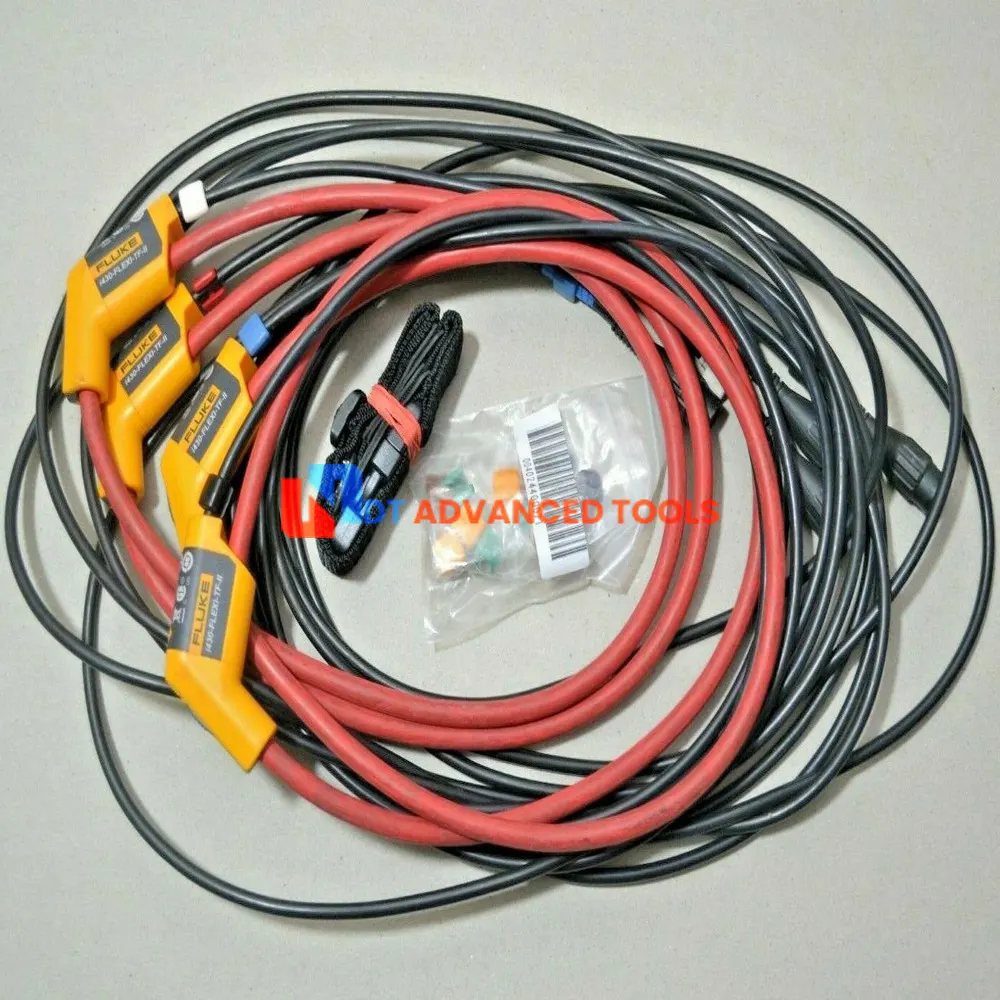
| Measure all three phases and neutral | With included four flexible current probes with enhanced thin flex designed to fit into the tightest places. |
| Automatic Trending | Every measurement is always automatically recorded, without any set-up. |
| System-Monitor | Ten power quality parameters on one screen according to EN50160 power quality standard. |
| Logger function | Configure for any test condition with memory for up to 600 parameters at user defined intervals. |
| View graphs and generate reports | With included analysis software. |
| Battery life | Up to 8 hours operating time per charge on Li-ion battery pack. |
Specifications
| Measurement Range | Resolution | Accuracy | |
| Volt | |||
| Vrms (AC + DC) | 1 V to 1000 V phase to neutral | 0.01 V | ± 0.1% of nominal voltage |
| Vpk | 1 Vpk to 1400 Vpk | 1 V | 5% of nominal voltage |
| Voltage Crest Factor (CF) | 1.0 > 2.8 | 0.01 | ± 5% |
| Vrms ½ | - | 0.1 V | ± 0.2% of nominal voltage |
| Vfund | - | 0.1 V | ± 0.1 % of nominal voltage |
| Amps (accuracy excluding clamp accuracy) | |||
| Amps (AC + DC) - i430-Flex 1x | 5 A to 6000 A | 1 A | ± 0.5% ± 5 counts |
| Amps (AC + DC) - i430-Flex 10x | 0.5 A to 600 A | 0.1 A | ± 0.5% ± 5 counts |
| Amps (AC + DC) - 1mV/A 1x | 5 A to 2000 A | 1 A | ± 0.5% ± 5 counts |
| Amps (AC + DC) - 1mV/A 10x | 0.5 A A to 200 A (AC only) | 0.1 A | ± 0.5% ± 5 counts |
| Apk i430-Flex | 8400 Apk | 1 Arms | ± 5% |
| Apk 1mV/A | 5500 Apk | 1 Arms | ± 5% |
| A Crest Factor (CF) | 1 to 10 | 0.01 | ± 5% |
| Amps½ - i430-Flex 1x | 5 A to 6000 A | 1 A | ± 1% ±10 counts |
| Amps½ - i430-Flex 10x | 0.5 A to 600 A | 0.1 A | ± 1% ±10 counts |
| Amps½ - 1mV/A 1x | 5 A to 2000 A | 1 A | ± 1% ±10 counts |
| Amps½ - 1mV/A 10x | 0.5 A A to 200 A (AC only) | 0.1 A | ± 0.5% ± 5 counts |
| Hz | |||
| Fluke 435 @ 50 Hz Nominal | 42.500 Hz to 57.500 Hz | 0.001 Hz | ± 0.01 Hz |
| Fluke 435 @ 60 Hz Nominal | 51.00 Hz to 69.00 Hz | 0.001 Hz | ± 0.01 Hz |
| Power | |||
| Watts (VA, var) - i430-Flex | Max. 6000 MW | 0.1 W to 1 MW | ± 1% ± 10 counts |
| Watts (VA, var) - 1 mV/A | Max. 2000 MW | 0.1 W to 1 MW | ± 1% ±10 counts |
| Power Factor (Cos j/DPF) | 0 to 1 | 0.001 | ± 0.1% @ nominal load conditions |
| Energy | |||
| kWh (kVAh, kvarh) - i430-Flex 10x | Depends on clamp scaling and V nominal | ± 1% ± 10 counts | |
| Energy Loss - i430-Flex 10x | Depends on clamp scaling and V nominal | ±1% ±10 counts Excluding line resistance accuracy | |
| Harmonics | |||
| Harmonic order (n | DC, 1 to 50 Grouping: Harmonic groups according to IEC 61000-4-7 | ||
| Inter-harmonic order (n) | OFF, 1 to 50 Grouping: Harmonic and Interharmonic subgroups according to IEC 61000-4-7 | ||
| Volts %f | 0.0 % to 100 % | 0.1 % | ± 0.1% ± n x 0.1% |
| Volts %r | 0.0 % to 100 % | 0.1 % | ± 0.1% ± n x 0.4% |
| Volts Absolute | 0.0 to 1000 V | 0.1 V | ± 5% |
| Volts THD | 0.0 % to 100 % | 0.1 % | ± 2.5% |
| Amps %f | 0.0 % to 100 % | 0.1 % | ± 0.1% ± n x 0.1% |
| Amps %r | 0.0 % to 100 % | 0.1 % | ± 0.1% ± n x 0.4% |
| Amps Absolute | 0.0 to 600 A | 0.1 A | ± 5% ± 5 counts |
| Amps THD | 0.0 % to 100 % | 0.1 % | ± 2.5% |
| Watts %f or %r | 0.0 % to 100 % | 0.1 % | ± n x 2% |
| Watts Absolute | Depends on clamp scaling and V nominal | - | ± 5% ± n x 2% ± 10 counts |
| Watts THD | 0.0 % to 100 % | 0.1 % | ± 5% |
| Phase Angle | -360° to +0° | 1° | ± n x 1° |
| Flicker | |||
| Plt, Pst, Pst(1min) Pinst | 0.00 to 20.00 | 0.01 | ± 5% |
| Unbalance | |||
| Volts | 0.0 % to 20.0 % | 0.1 % | ± 0.1% |
| Amps | 0.0 % to 20.0 % | 0.1% | ± 1% |
| Mains signaling | |||
| Threshold levels | Threshold, limits and signaling duration is programable for two signaling frequencies | - | - |
| Signaling frequency | 60 Hz to 3000 Hz | 0.1 Hz | - |
| Relative V% | 0 % to 100 % | 0.10 % | ± 0.4% |
| Absolute V3s (3 second avg.) | 0.0 V to 1000 V | 0.1 V | ± 5% of nominal voltage |
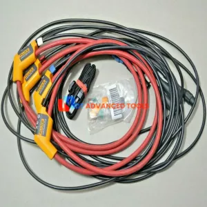
Included:
- Fluke 435 II Power Quality and Energy Analyzer
- Fluke AC to DC Power Supply Charger
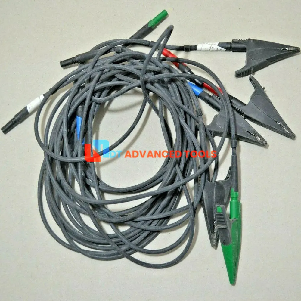
- 5 x Fluke Lead Set
- 5 x Fluke Lead Alligator Clips
- 4 x Fluke i430-FLEXI-TF-II Current Loops
- Hard Transport Case
Download
Fluke 434-II, 435-II, 437-II Series II User Manual.PDF
Fluke 435-II Series II Three-Phase Power Quality and Energy Analyzer Datasheet.PDF
Fluke 435-II Series II Three-Phase Power Quality and Energy Analyzer Brochure.PDF