GE Inspection Phasor XS Phased Array Ultrasonic Flaw Detector NDT
Sell used GE Inspection Phasor XS Phased Array Ultrasonic Flaw Detector. Used in very good and fully working condition.
Condition: Used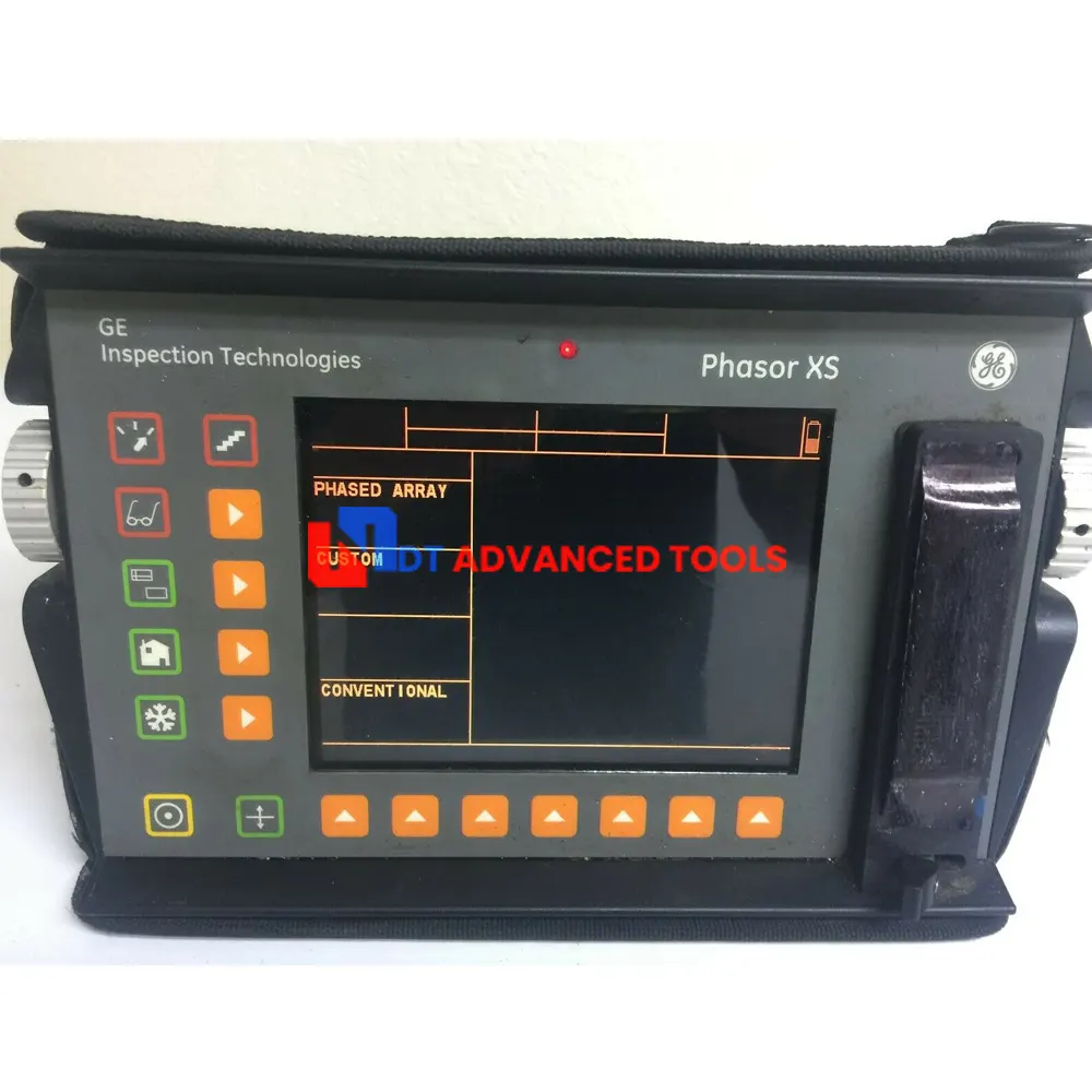


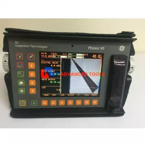
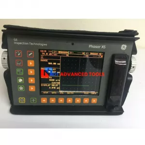
Up for sale GE Inspection Phasor XS Phased Array Ultrasonic Flaw Detector. Used in very good and fully working condition.
Pakcages includes:
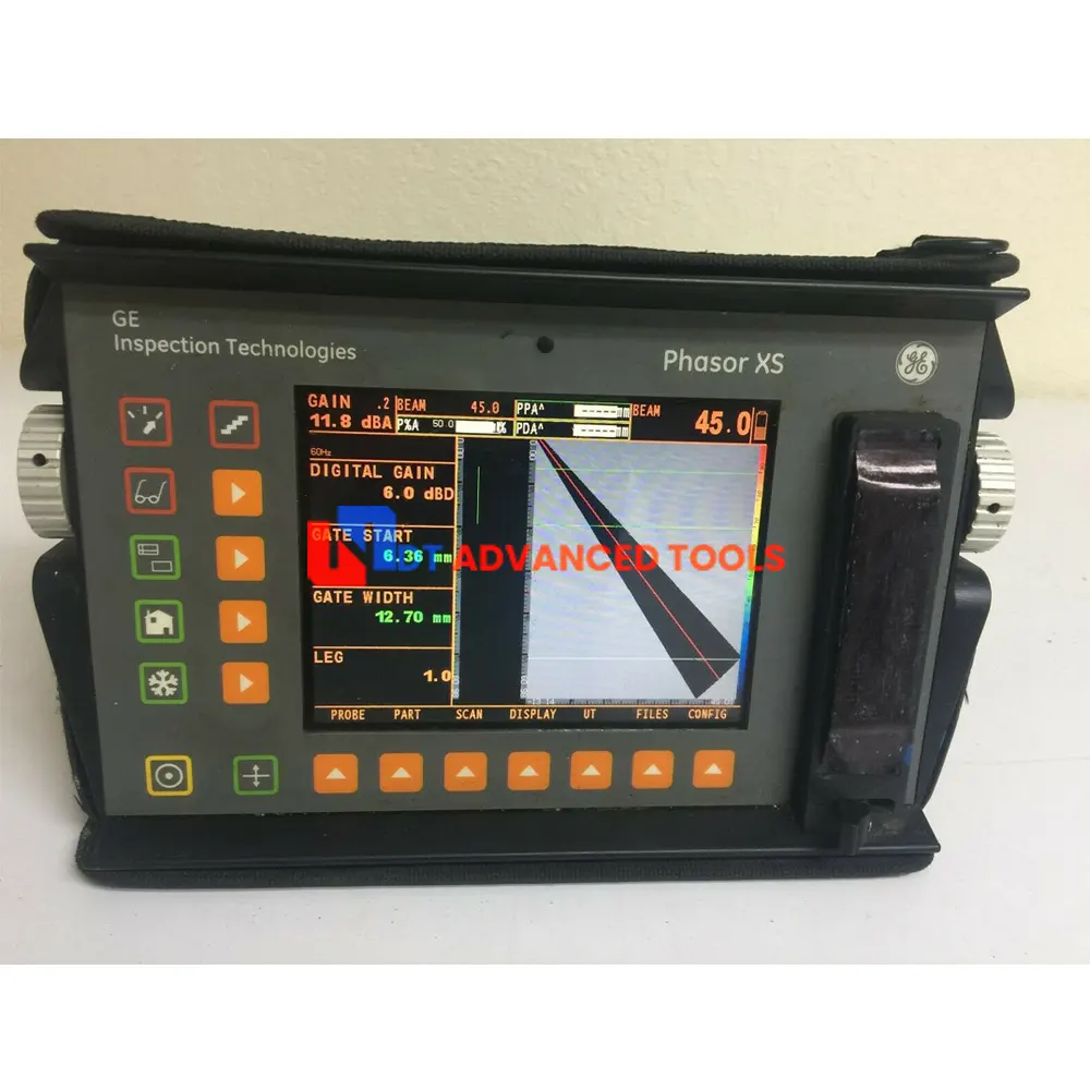
- GE Inspection Phasor XS unit
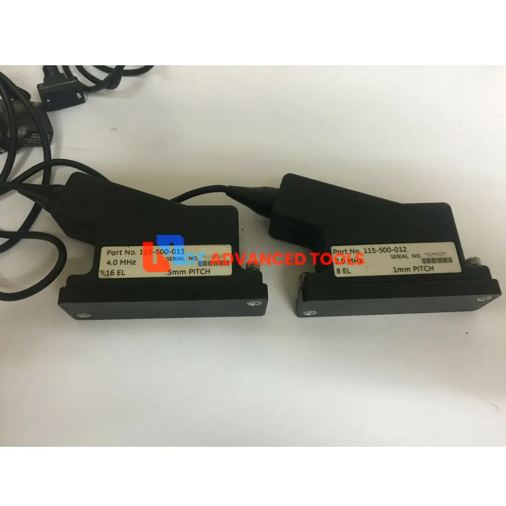
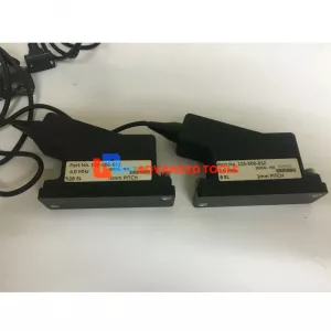
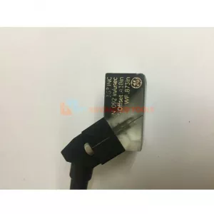
- Transdusers 2.0MHz (115-500-012)
- Transdusers 4.0MHz (115-500-013)
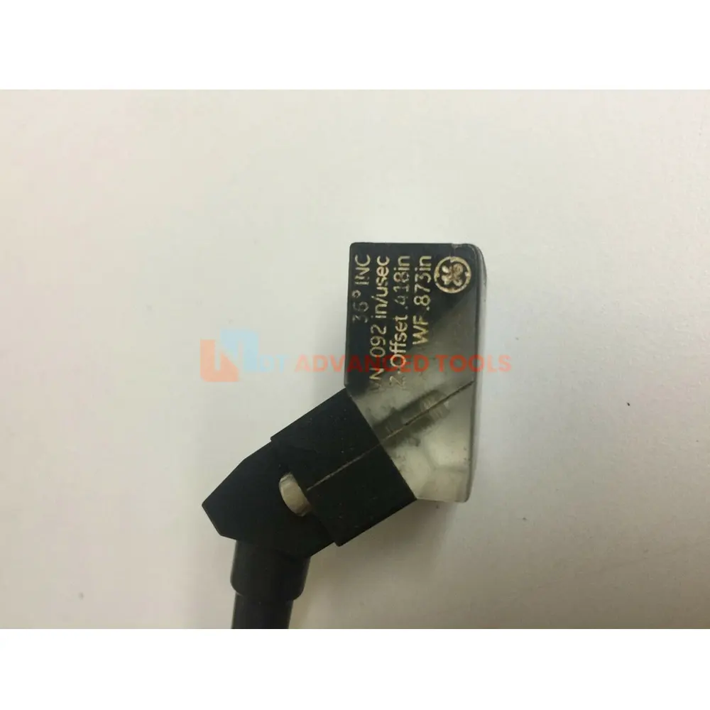
- Wedge
- Battery pack
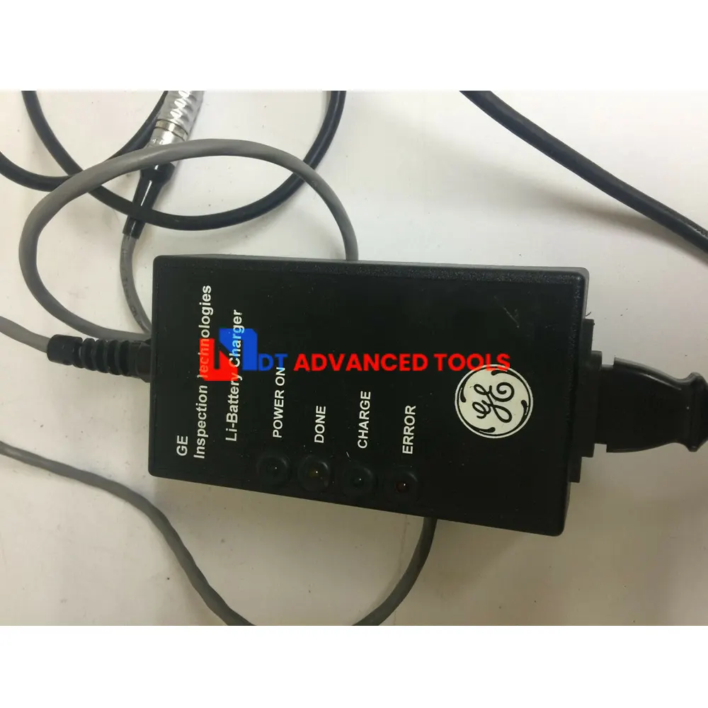
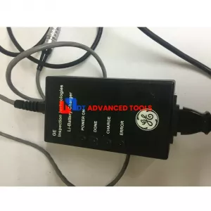
- AC adapter/charger
- User Manual on CD-ROM
- Carrying Case
The GE Phasor XS brings the proven advantages of Phased Array technology to a new – and accessible – level. This portable and rugged device combines the value of Phased Array with a code-compliant conventional UT flaw detector. It is simple to use, easy to learn and specially designed with practical, relevant features.
When used in Phased Array mode, the operator can electronically control multiple beams from one probe. The precise beam control
including angle, focus and size, results in improved probability of detection (POD) and sizing. With one scan from one contact
location, greater area is covered and comprehensive data can be viewed in real time on a full color sector display. When compared to conventional Ultrasonic inspection, the productivity and cost savings from the Phasor XS are easily measured.
Productivity gains
When the inspection requires a different angle with conventional ultrasonic testing, the operator must change his probe and re-visualize the integration of the new information. A different time base and sensitivity level is represented. Although this is not a problem for the skilled operator, it takes time. Through the power of Phasor XS, these inefficiencies are drastically minimized.
Real time color imaging from the Phasor XS supplies an integrated cross-sectional visualization of the part originating from multiple angles. A single A-Scan can also be selected for display in combination with the image. With a single probe, you can achieve more than ever before – and in less time.
Overall, the Phasor XS provides:
- Improved area coverage, faster results
- More information from one scan of the part
- Better recorded result from the generation of an image
- One probe replicates the capabilities of many conventional UT probes and wedges
- Time and cost savings from reduced hours evaluating indications with multiple angles
Measurable time savings
Some weld inspections require a complete scan with three separate angles. Using the Phasor XS can result in a time savings of two thirds.
Test quality improvements
Defect orientation is a prediction made in the development of a test procedure and an inspection angle is chosen based on this prediction. Beam spread is chosen purposely broad to account for some level of error in the prediction, so essentially it is a compromise.
With the Phasor XS, electronic control of the beam allows test procedures to be developed that will yield higher Probability of Detection (POD), in the same inspection time, by allowing the choice of an ideal beam over the full inspection area. The quality of the scan is improved and the Phasor XS’ full-color, real time sector display with selectable A-Scan supplies the standard accepted method for instant and reliable sizing.
Simple change over
Building Phased Array capabilities into a successful proven operating platform ensures the transition to Phased Array inspection will be cost effective. Phasor XS’ simple menu driven operation of basic Phased Array controls puts the technology within reach of the Level II field inspector. Data is easily interpreted and the cost of training is minimal.
Standard Features
An on board data set memory is combined with removable storage via an SD card for documentation and setup storage. This ensures your operators will be working with consistent setups to get brilliant results that you can see later on the screen or computer.
The unique Sector Freeze mode allows review and storage of all the A-Scans behind the image. Select your beam of interest from all of the shots for separate display and improve your sizing with focal and angle control.
- Combined Phased Array and code compliant Conventional UT flaw detector
- Truly portable Phased Array – less than 4 kg (7 lbs)
- Electronically controlled and selectable beam angles, focus and size
- Simultaneous inspection with multiple beams from a single location
- Full color, real time sector display with a selectable ASCAN
- Fullscreen Bscan plus Display reverse and flip
- Rugged packaging to withstand heavy onsite use
- Snap shot image storage of sector images and ASCANS
- ialog probes 16/64
- Delay law calculator
- Push button control for operation in a bag
- Simple operating scheme
- Image transfer via SD card
GE Inspection Phasor XS Technical Specifications
| Display Size Resolution | 6.5 inch VGA (640*480 pixel) color TFT, 60Hz refresh rate |
| Battery Type | Custom Li-Ion battery pack (3S6P configuration) |
| Battery Life | 4 hours minimum |
| Battery Charging | External charger that connects directly to the battery pack |
| External Power Supply | Universal input (85 – 265V / 50 – 60 Hz) |
| Units of Measure | inch and mm |
| SD Card Memory | Sealed compartment |
| Number of Cycles Focal laws | 128 (max) |
| Pulse repetition Frequency | 15 to 7680Hz |
| Pulser Type | Bipolar Squarewave |
| Pulser Voltage | +/-25V to +/-75V |
| Pulser Energy | N/A |
| Pulser Rise Time | Not Specified |
| Damping | N/A |
| Dual Mode | N/A |
| Bandwidth/ Amplifier bandpass |
0.5 to 10MHz |
| Direct Documentation format |
JPEG |
| Probe Connections |
Custom Supplied |
| Physical Probe | 1 to 64 |
| Virtual Probe | 1 to 16 |
| Number of Cycles | 1 to 128 |
| Pulser Width (1/2 cycle) | 40 to 500ns |
| Pulser Delay | 0 to 10.24us |
| Receiver Delay | 0 to 10.24us |
| Receiver Input Resistance | 220ohm |
| Analog Gain | 0 to 40.0dB |
| Digital Gain | 0 to 50.0dB |
| Frequency Select | 2.25MHz, 5MHz, LP and HP |
| Rectification | PosHW, NegHW and Fullwave |
| Measurment Resolution | 5nsec |
| Displayed Readings | A%A, A%B, SA/, SA^, SB/, SB^ |
| VGA output | Yes |
| SD Card Memory | Yes |
| RS 232 interface |
Yes |
| Auto Timebase Calibration |
No |
| Reject |
0 to 80% |
| TCG |
16 points (max) - 6dB/usec |
| Sound Velocity |
.0393 - .5905”/us[1000 – 15000m/s] |
| Range | 1m @ steel shear velocity |
| Display Delay | 1m @ steel shear velocity |
| Gates | A,B,IF |
| Gate Threshold |
5% to 95% |
| Gate Start | 0.1mm to 1m |
| Gate Width | 0.1mm to 1m |
| TOF Modes |
Flank, Peak |
| Scan type |
Linear or Sector |
| Data visualiztion refresh rate |
60Hz |
| Available views |
Ascan only, Image only, Ascan + Image |
| Dialog Languages | English, Spanish, German, French, Chinese, Japanese |
| Dimensions (W x H x D) | 11.1 x 6.75 x 6.25 inch (282 x 171 x 159 mm) |
| Weight | 7.5lbs (with batteries) |
|
Environmental Tests |
|
| Cold Storage |
-20C for 72 hrs, 502.4 Procedure I |
| Cold Operation |
0C for 16 hrs, 502.4 Procedure II |
| Heat Storage | +70C for 48 hrs, 501.4 Procedure I |
| Heat Operation | +55C for 16 hrs, 501.4 Procedure II |
| Damp Heat / Humidity (storage) | 10 Cycles: 10hrs at +65C down to +30C, 10 hrs at +30C up to +65C, Transition within 2 hrs, 507.4 |
| Temperature Shock | 3 Cycles: 4 hrs at –20C up to +70C, 4 hrs at +70C, Transitions within 5 minutes, 503.4 Procedure II |
| Vibration | 514.5-5 Procedure I, Annex C, Figure 6, General exposure: 1hr each axis |
| Shock | 6 cycles each axis, 15g, 11ms half sine, 516.5 Procedure I |
| Loose Cargo | 514.5 Procedure II |
| Transit Drop (packaged for shipment) | 516.5 Procedure IV, 26 drops |
| Environmental Sealing Tests |
|