Olympus EPOCH 650 Phased Array Ultrasonic Flaw Detector
The EPOCH 650 design is focused on providing a very high level of flaw detection with the simplicity of a basic instrument.
Condition: New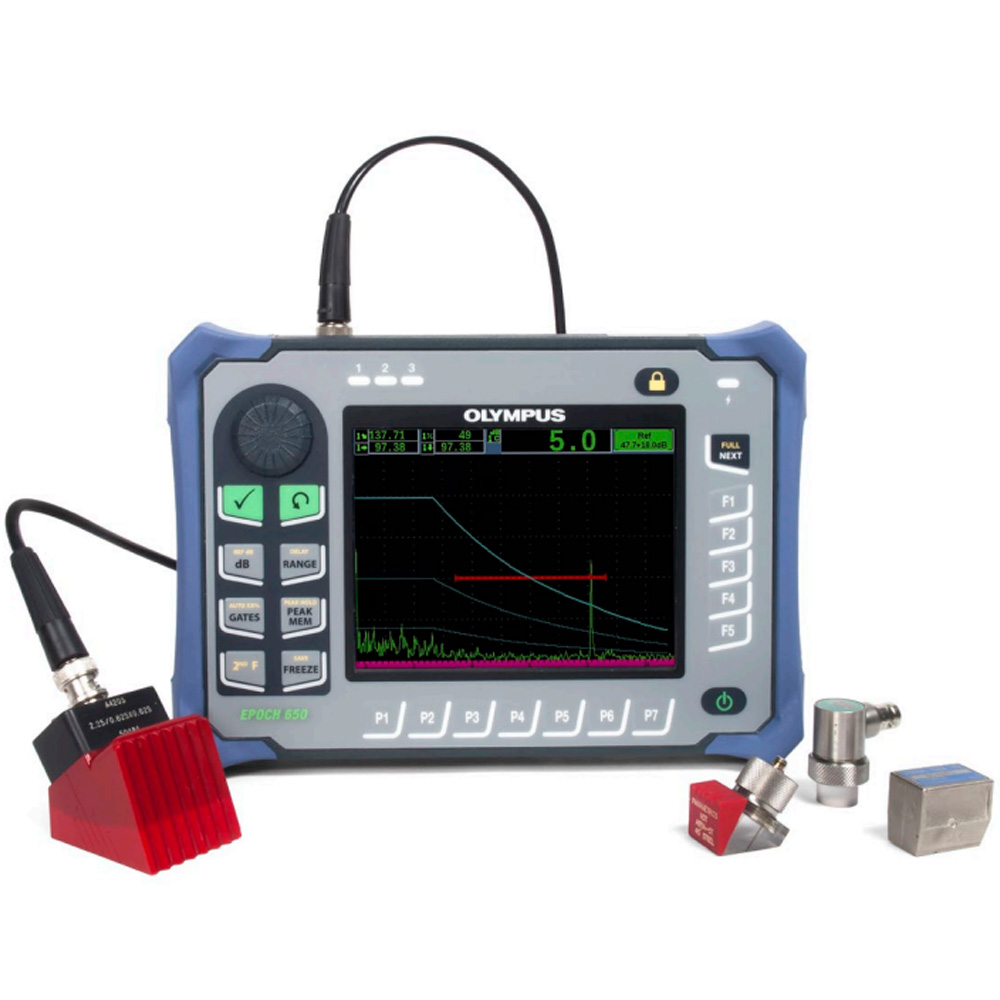


Economical Size, Quality Performance
The large, full VGA transflective display combined with our patented digital high dynamic range receiver provides a stable, striking A-scan representation in any lighting condition. The EPOCH 650 is designed to meet the requirements of ISO 22232-1 and allows a full range of standard and optional flaw detection features. Multiple onboard reporting tools and a comprehensive data filing system enable you to easily collect and report high quality inspection data. The rugged, ergonomic design allows use in nearly any inspection environment, while the flexible PerfectSquare™ pulser and highest number of digital filters in its class can tackle nearly any application.
The EPOCH 650 Digital Ultrasonic Flaw Detector combines Olympus’ industry leading conventional flaw detection capabilities with the efficiency of a highly portable, intuitive instrument. The EPOCH 650 flaw detector’s blend of efficient menus and direct access keys allows you to take advantage of the highest quality flaw detection platform with exceptional ease of use.
Designed for All Inspection Environments
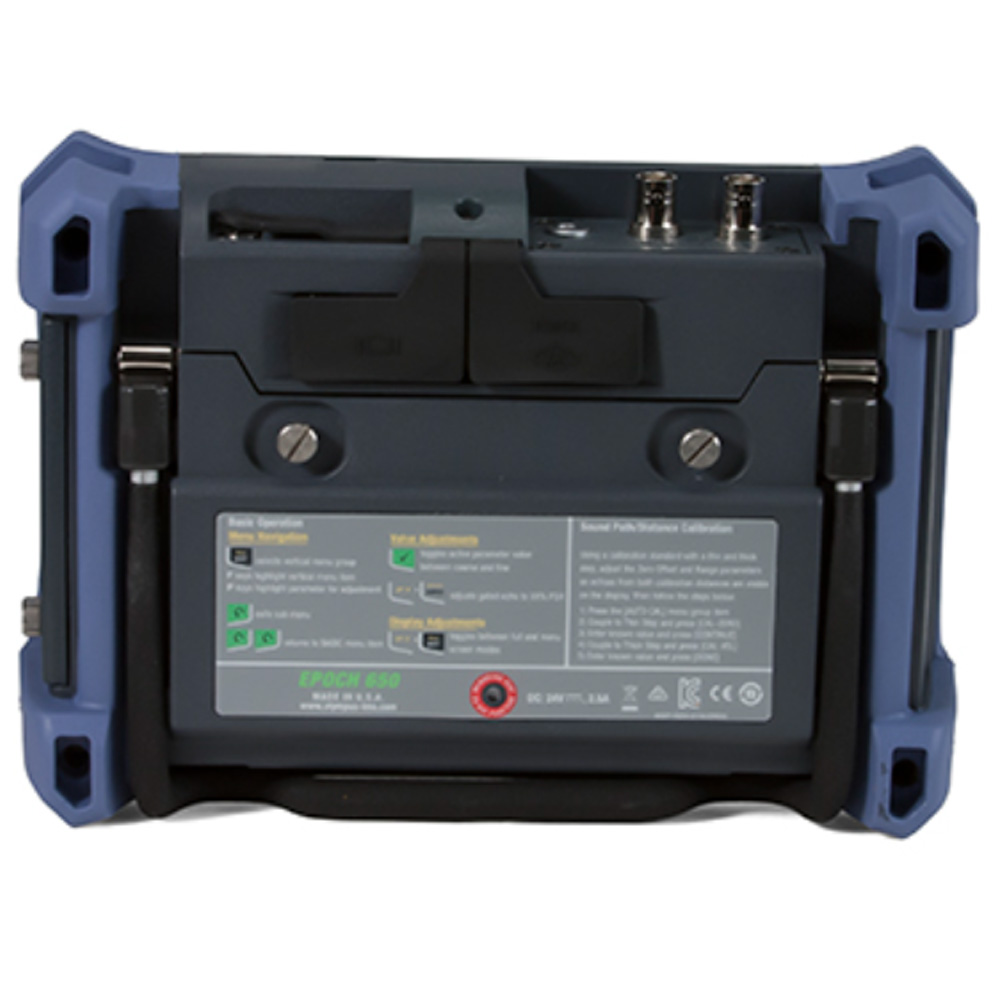
The EPOCH 650 is designed for use in nearly any inspection environment, from bench top testing in a laboratory to extreme outdoor and hazardous conditions. Designed for IP rating in either knob (IP66) or navigation pad (IP67) configurations, and tested to very high environmental and reliability standards, the EPOCH 650 allows users in any inspection environment to feel confident in both the performance and durability of the instrument.
Simple and Comfortable Operation
The EPOCH 650 design is focused on providing a very high level of flaw detection with the simplicity of a basic instrument. The EPOCH 650 is designed to be ergonomic, intuitive, and practical for both experienced and novice ultrasonic inspectors.
Intuitive User Interface
The EPOCH 650 user interface is based on the industry leading EPOCH 600 flaw detector. The EPOCH 650 combines a simple menu structure for instrument settings, calibration and software feature adjustment, with the EPOCH brand’s hallmark direct-access key approach for critical inspection functions such as gain and gate adjustment, screen freeze, and file save. Supported in multiple languages, the EPOCH 650 user interface is intuitive for any level of operator.
Vibrant VGA Display with Full Screen Mode
The EPOCH 650 features a full VGA (640 x 480 pixels) resolution display. The horizontal design of the EPOCH 650 optimizes the A-scan size and readability on this high quality display. Built with transflective technology, this VGA display provides excellent clarity in indoor, low lighting conditions using its powerful backlight, as well as in direct sunlight by using the ambient light as a pseudo-backlight.
The full screen mode feature enhances this vibrant display to provide the largest A-scan in an EPOCH series flaw detector!
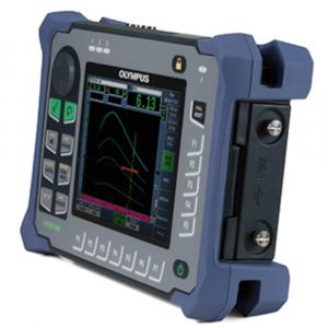
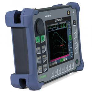
Options for Comfortable Navigation
In order to accommodate different user needs and preferences, the EPOCH 650 is available in two hardware configurations:
Knob
The adjustment knob on the EPOCH 650 is used along with the CHECK and ESC keys to adjust parameter values in either coarse or fine increments. You have the ability to lock the knob to prevent accidental parameter value changes during an inspection. This configuration provides smooth value slewing for customers who prefer adjusting parameters using a knob. The knob configuration is designed to meet the requirements of IP66.
Navigation Pad
The EPOCH 650 navigation pad is a hallmark feature of the EPOCH flaw detectors. The up and down arrows on the navigation pad are used for coarse parameter adjustment, and the left and right arrows for fine adjustment. The navigation pad also contains additional functions and frequently used parameters such as gain, save, and the CHECK and ESC keys. The navigation pad configuration is designed to meet the requirements of IP67.
Key Features
- Designed to meet the requirements of ISO 22232-1
- PerfectSquareTM tunable square wave pulser
- Full screen A-scan mode
- Digital high dynamic range receiver
- Thirty digital filters for enhanced signal-to-noise ratio
- 2 kHz PRF for rapid scanning
- Knob or navigation pad adjustment configurations
- Large, full VGA sunlight readable display
- 15+ hours of battery life
- Standard dynamic DAC/TCG and onboard DGS/AVG
- Multiple on-board report formats
- MicroSD memory card for data transfers
- Optional Corrosion Module software with Encoded B-scan
- USB On-The-Go (OTG) for PC communication
- Alarm and VGA outputs
- Optional analog output
Specification
|
GENERAL |
|
| Display type | Full VGA (640 x 480 pixels) transflective color LCD, 60 Hz update rate |
| Display dimensions (W x H x D) | 117 mm x 89 mm, 146 mm |
| Keypad | English, International, Japanese, Chinese |
| Languages | English, Spanish, French, German, Japanese, Chinese, Portuguese, Russian |
| Transducer connections | BNC or Number 1 LEMO |
| Data storage | 100,000 IDs onboard, removable 2 GB MicroSD card (standard) |
| Battery type | Single lithium-ion rechargeable standard |
| Battery life | 15 h to 16 h (lithium-ion) |
| Power requirements | 100 VAC to 120 VAC, 200 VAC to 240 VAC, 50 HZ to 60 Hz |
| Overall dimensions (W x H x D) | 236 mm x 167 mm x 70 mm |
| Weight | 1.6 kg |
| INSTRUMENT INPUTS / OUTPUTS | |
| USB Ports | USB On-The-Go (OTG) |
| RS-232 Port | Yes |
| Video Output | VGA output standard |
| Analog Output | 1x analog output (optional), Selectable 1 V/10 V Full Scale, 4mA max |
| Alarm Output | 3 alarm outputs, 5 V TTL, 10 mA |
| Trigger I/O | Trigger input, 5V TTL; Trigger output, 5V TTL, 10 mA max |
| Encoder Inputs | 1-axis encoder line (quadrature - Corrosion Module mode only) |
| RECEIVER | |
| Gain | 0 to 110 dB |
| Maximum input signal | 20 V p-p |
| Receiver input impedance | 400 Ω ± 5% |
| Receiver bandwidth | 0.2 MHz to 26.5 MHz at -3 dB |
| Digital filter settings | Thirty digital filter sets standard Seven ISO 22232-1:2020 compliant filters (0.2-10 MHz, 2.0-21.5 MHz, 8.0-26.5 MHz, 0.5-4 MHz, 0.2-1.2 MHz, 1.5-8.5 MHz, 5-15 MHz) |
| Rectification | Full-wave, Positive Half-wave, Negative Half-wave, RF |
| System linearity | Horizontal: ± 0.5% FSW |
| Resolution | 0.25% FSH, amplifier accuracy ± 1dB |
| Reject | 0 to 80% FSH with Visual Warning |
| Amplitude measurement | 0 to 110% full screen height with 0.25% resolution |
| Measurement rate | Equivalent to PRF in all modes |
| PULSER | |
| Pulser | Tunable Square Wave |
| PRF | 10 Hz to 2000 Hz in 10 Hz increments |
| Energy settings | 100 V, 200 V, 300 V or 400 V |
| Pulse width | Adjustable from 25 ns to 5,000 ns (0.1 MHz) with PerfectSquare™ technology |
| Damping | 50, 100, 200, 400 Ω |
|
CALIBRATION |
|
| Automated calibration | Velocity, Zero Offset, Straight Beam (First Backwall or Echo-to-Echo), Angle Beam (Soundpath or Depth) |
| Test modes | Pulse Echo, Dual, or Through Transmission |
| Units | Millimeters, inches, or microseconds |
| Range | 3.36 mm to 13,388 mm (0.132 in. to 527.10 in.) @ 5,900 m/s (0.2320 in./μ) |
| Velocity | 635 m/s to 15240 m/s (0.0250 in./µs to 0.6000 in./µs) |
| Zero offset | 0 µs to 750 µs |
| Display delay | -59 mm to 13,401 mm (-2.320 in. to 526.97 in.) @ longitudinal velocity in steel |
| Refracted angle | 0° to 90° in 0.1° increments |
|
GATES |
|
| Measurement gates | 2 fully independent gates for amplitude and TOF measurements |
| Gate start | Variable over entire displayed range |
| Gate width | Variable from Gate Start to end of displayed range |
| Gate height | Variable from 2 to 95% full screen height |
| Alarms | Positive and Negative Threshold, Minimum Depth (Gate 1 and Gate 2) |
| MEASUREMENT | |
| Measurement display locations | 5 locations available (manual or auto selection) |
| Gate (1, 2) | Thickness, Soundpath, Projection, Depth, Amplitude, Time-Of-Flight, Min./Max. Depth, Min./Max. Amplitude |
| Echo-to-Echo | Standard Gate 2-Gate 1, Optional IF Gate Tracking |
| Other measurements | Overshoot (dB) value for DGS/AVG, ERS (equivalent reflector size) for DGS/AVG, AWS D1.1/D1.5 A, B, C and D values, Reject Value, Echo to RefdB values |
| DAC/TCG | Standard |
| DAC points | Up to 50 points, 110 dB dynamic range |
| Special DAC modes | Custom DAC (up to 6 curves), 20-80% View |
| Curved surface correction | Standard OD or Bar correction for Angle Beam measurements |
| Corrosion | Zero-cross measurement algorithm, V-Path correction, Single or Echo-to-Echo, Encoded B-scan |
|
ENVIRONMENTAL RATINGS |
|
| IP Rating | Designed to meet the standards of the Ingress Protection (IP) rating number IP67 (navigation pad version) or IP66 (knob version) per IEC 60529-2004 (Degrees of Protection provided by enclosures – IP Code).
The product design was confirmed to meet the IP rating by means of Olympus internal design verification test process that occurs prior to the release of the product to production. |
| Explosive Atmosphere | Safe operation as defined by Class I, Division 2, Group D, as defined in the National Fire Protection Association Code (NFPA 70), Article 500, and tested using MIL-STD-810F, Method 511.4, Procedure I. |
| Shock Tested | MIL-STD-810F, Method 516.5 Procedure I, 6 cycles each axis, 15g, 11 ms half sine. |
| Vibration Tested | MIL-STD-810F, Method 514.5, Procedure I, Annex C, Figure 6, general exposure: 1 hour each axis |
| Operating Temperature | –10 °C to 50 °C (14 °F to 122 °F) |
| Battery Storage Temperature | 0 °C to 50 °C (32 °F to 122 °F) |
Included:
- EPOCH 650 Digital ultrasonic flaw detector
- Battery
- Charger/AC adapter
- Rechargeable lithium-ion battery
- USB cable
- Quick reference card
- Comprehensive operation manual (CD)
- Transport case